How To Weld A Sheet Metal Corner Shut In Inventro

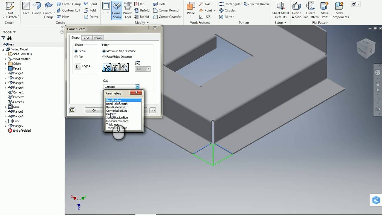
Inventor Sheet Metal Corner Seam Tool Youtube
Bend Relief Big Holes Autodesk Community Inventor

Corner Seam In Sheet Metal Parts Autodesk Community Inventor

Inventor Sheet Metal Corner Relief Options Youtube

Weld To Seal Flange Autodesk Community

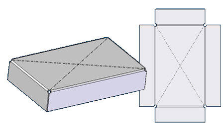
Inventor Sheet Metal Trailer Box Youtube
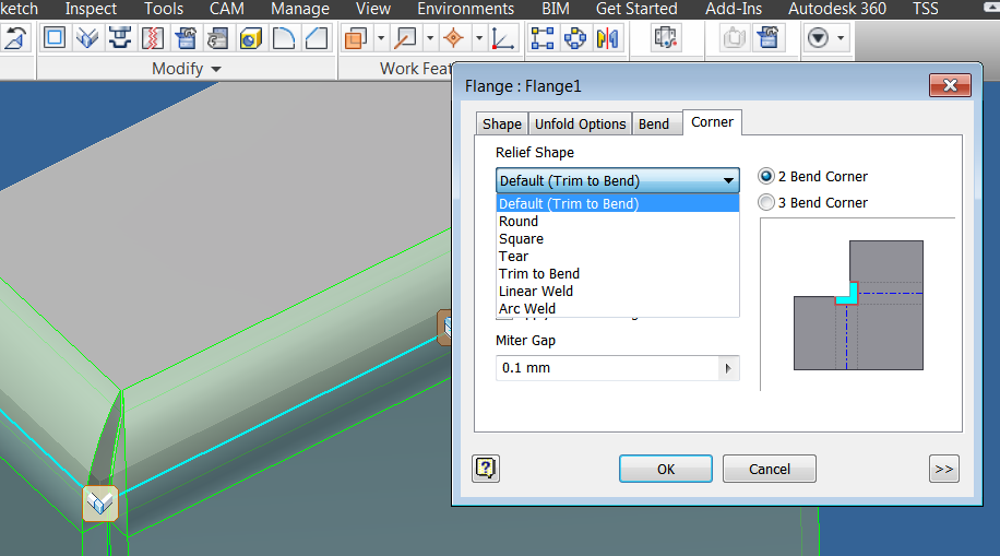
Overrides default parameters that define how corners are relieved when a folded model is unfolded.
How to weld a sheet metal corner shut in inventro.

Miter Sheet Metal Corner Help Autodesk Community Inventor

How Do You Close Off A Flange With Sheet Metal Autodesk Community Inventor

Solved Problem With Sheet Metal Corners After Adding Corner Seam With Overlap Autodesk Community Inventor
Inventor Sheet Metal Corner Seam B Youtube

Inventor Sheet Metal Folds Youtube

Inventor Sheet Metal Change A Bend To A Corner Youtube

Solved Sheet Metal Rounded Corner Sink Autodesk Community Inventor

Sheet Metal Design For Welding Autodesk Community Fusion 360

Inventor Sheetmetal Corner Seams

Solved Sheet Metal Part With Flanges Over A Curved Surface Autodesk Community Inventor

Solved Inventor Can T Make Complete Flat Pattern After Corner Seam Autodesk Community Inventor

Solved How Do I Flat Pattern My Parts In Inventor Autodesk Community Inventor

Solved Sheet Metal Contour Flange Miter Of Different Bodies Autodesk Community Inventor

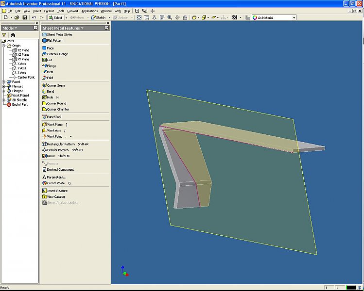
Flange Feature In Inventor 2015 Youtube

Youtube Solidworks Tutorial Solidworks Metal Box

Pin On Solidworks

Solved How To Close Gap At Corner Autodesk Community Inventor

What Are The Unique Sheetmetal Features That Are Available In Inventor Autodesk Community Inventor
Sheet Metal Self Intersecting Flanges Error Autodesk Inventor Autocad Forums

Autodesk Inventor Sheet Metal Tutorial Basics Youtube Autodesk Inventor Metal Furniture Design Solidworks Tutorial

Sheetmetal Default Corner Relief Miter Gap Autodesk Community Inventor

Autodesk Inventor Sheet Metal Flat Pattern Success Every Time Sheet Metal Sheet Metal Fabrication Sheet Metal Work

Exploring The Options Of The Contour Roll
Cross Brake Stiffening Bend Autodesk Community Inventor
Source : pinterest.com
